A logical diagnostic process...

cantflip

Old Jagoff with a Hat
FCBO Gold Member
Joined
Nov 1, 2015
Messages
10,978
Reaction score
12,160
Location
Orlando, FL
I am borrowing the symptoms from C1's door lock issue, but I didn't want to hijack his thread. I have finished for now, but will use this thread to continue with any other diagnostic help that comes to mind. Please feel free to add here, it is my hope this will be a good reference for someone trying to figure out electrical issues.

1st you need to start with as complete a set of symptoms as you can. What works and what doesn't or doesn't work correctly. Electrical circuits often share power and/or ground connections with other systems and the symptoms help you use a schematic to narrow in on the problem areas.

2nd with a good understanding of symptoms scan, print and trace the flow of electricity through the problem component. Some schematics are complex, so don't do this in the book... you may want clean copies for future use. While following/tracing powerflow, I find highlighters are helpful as well as a few colors so you don't get things mixed up. First highlight the load(s) in your circuit with one color. Before the load is + after the load is -, make them different colors. Controls can be + or - side or both. If 2 or more loads are in series you don't get - until after the last load, and the loads will divide the voltage between them. use a different color between loads in series... I am not going to address that here, but can after.

This concern starts at the symptoms of the driver's door lock doesn't lock or unlock from any switch, but all other door locks work fine. Also noted is when cycling the lock switch several times, all locks go dead for a moment. The power seats run slow too. The door does lock and unlock with the key.
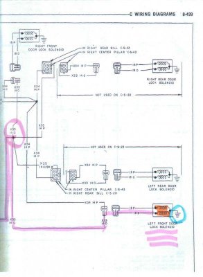
C_49 Power Door Llock System.jpgC Wiring 8_439.jpg

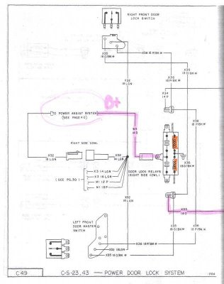
I only highlighted the one circuit, this schematic doesn't show if it is for lock or unlock... but that doesn't matter because neither work at this actuator. The switch side of the relay works all locks together, because the other locks work, I can eliminate the switch all control circuits to the relay(coil side), the relay itself works. The problem MUST be after the splice and because these circuits do not change polarity like a reversible motor actuator it cannot be a wire causing both lock and unlock to fail. UNLESS the actuator has a ground wire, it is not clearly drawn as case ground.

The only logical conclusion as to why the lock actuator wont lock or unlock electronically is a ground issue or a failed actuator.

If the lock mechanism was jammed and not moving, the electrical possibility would not be addressed until the mechanical issue was diagnosed.

Either way the door panel has to come off because there is no connector to isolate the driver door lock actuator outside the door.

C_49 Power Door Llock System.jpg


C Wiring 8_439.jpg
 
Last edited:
The symptom of the door locks stop working for a moment after cycling the switch several times may well be normal operation.

C Wiring 8_429.jpg

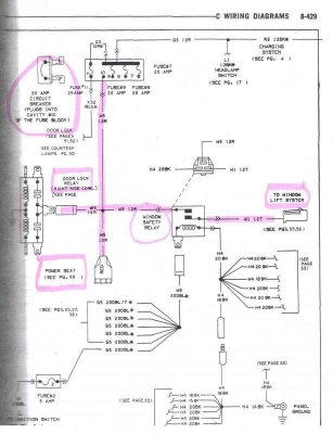
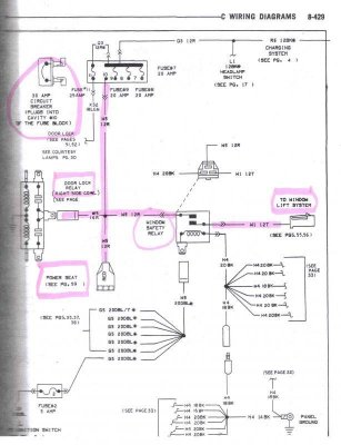
This schematic is the continuation from the place I marked B+ on the last set. It shows that power to the lock actuators comes from the 30 amp circuit breaker at position 10 of the fuse panel. A circuit breaker works like a self resetting fuse in this case, by cycling the lock switch it is possible to trip the breaker... which resets after a moment to cool down.

The schematic also shows this same circuit breaker provides B+ to the power seat and window motors. If the seats and/or windows tend to stop for a break during operation... that indicates the breaker may be weak. Bi-metallic breakers like this eventually break one piece of metal and stop working... always open OR always closed(no protection) in a newer car there would be a bigger fuse (40 amp or more) upstream. It is not a bad safety measure to check this breaker from time to time because you have no other upstream protection than a fusible link towards the alternator (rated 100 amp). If you can make it open, by holding a switch for a several seconds, it is providing protection. Choose a switch with a motor, not a solenoid, the motor at the end of its run will increase current draw... a solenoid won't.

If the breaker is weak, it should be a cheap replacement.

Back to the concern of the driver's door lock doesn't unlock or lock. IF this function is the only one to trip the breaker, it would indicate low resistance in the solenoid(load) or a short. A dead short with no resistance should open the breaker immediately. Looking back to the schematic of the solenoid, it is actually 2 windings... 1 for lock and 1 for unlock... to not work in both directions and to trip the breaker... something is shorting the windings. Either they have shorted together or a piece of metal broke free in the actuator shorting them both.

I have taken a few liberties assigning more symptoms than I actually have, so this may not fully match C1's problem.
I hope it helps anyone who is having trouble see how much a wire schematic and symptoms are really used to diagnose, I haven't even seen the car and could, with complete symptom information, diagnose most likely cause(s).

C Wiring 8_429.jpg
 
Last edited:
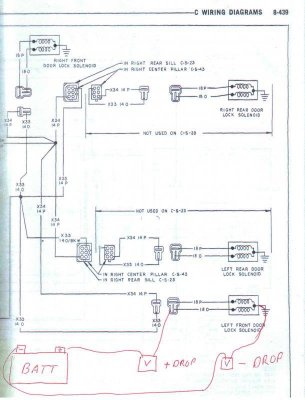
It is always wise to voltage drop circuits before reassembling the trim. While the door panel is off voltage drop the lock actuator by attaching your DMM lead to one of the power wires (Purple or Orange) WITHOUT disconnecting the connector (back probe). Using a fused jumper wire to connect the other DMM lead to the battery + terminal. WHILE OPERATING the actuator, your DMM should read about .5 volts or less.

While doing this test you will have to try both switch positions because they are not marked. One switch position wont change, the other is your drop measurement. If the drop is much higher than .5 volts there is a resistance problem on the circuit.

Test the other power circuit (Purple or Orange) the same way, just move your back probe and you are all set. This one should read with the switch opposite that last test. You still don't want more than .5 volts drop.

Test your ground connection by removing the back probe, changing the battery connection to the - terminal and touching the actuator(if case grounded) with your lead while operating the door locks. If the actuator has a ground wire, back probe there for this test. If more than .5 volts are dropped, the ground circuit has too much resistance.

C Wiring 8_439 B.jpg

I prefer to have a photo copy of the diagram in hand for these tests. I draw in my test locations and then I write my reading on the voltmeter. I find this helpful if I am testing a lot of locations so I can keep my readings straight. I only drew one of the + and the - voltage drop I described above so the schematic didn't get too confusing. When its you doing this, try not put so much information on one picture that you can't make sense of it.

IDEAL VOLTAGE DROP is .5 volts...less is better. If you are dealing with a 40 year old car with 100K miles, chances are non of your tests will be "in spec". If you note the voltage drops, you can later decide if a circuit is working "good enough". You can make yourself crazy trying to make all connections clean and in spec, but that's really not necessary.

A FUSED JUMPER WIRE is a length of wire with a fuse holder and a small fuse 5 amp is good. The fused end should be the side connected to the battery, that way if you damage the jumper wire or accidentally short it, you will blow the fuse before damaging anything.

BACK PROBES are any device that lets you make contact with the terminal without disconnecting or damaging anything. Lots of mechanics have found wire piercing probes to be easier than back probing. I hate wire piercing probes because they cause damage to the wire strands and insulation and often cause the next failure. There are so many connector styles that you will have to get a little creative here. Some terminal connectors are open at the back and are easy to probe with a paperclip, some have a rubber seal that a sewing needle can get by without damage. If the wire terminal is molded to the wire, sometimes we make little jumper leads to get a test point. just be gentile and cautious so you don't make new problems.

TO DIAGNOSE A FAILED TEST. The reason I voltage drop from the battery is, if it passes, the entire circuit has been proven and no more testing is required. If the voltage drop is too high (.5 volts) find the easiest access points to the circuit in between the battery and the actuator. Retest where its easy to get to and write your readings on the copied schematic. The schematic makes it easy to sit down and decide what the new reading eliminated. This is often called "eliminate what's good". The more you can narrow in on the problem area the better. Ultimately you may have to replace some of the wiring, it would be far better to only replace what's bad.

C Wiring 8_439 B.jpg
 
Last edited:
I have to run...already a little late... I will edit some basic voltage drop tests here, which can be used to prove out the wires are capable of handling the current of these actuators. A very wise test to do before reassembling the door.

You lost me at Logical.....

image.jpg
 
Back to my scenario where the seats are slow. If you use the voltage drops from the door lock, the window and the seats you could find only the seats have too much voltage dropped. Looking at the schematic, if the other systems are in spec, the bad wire would have to be from the splice to the seat circuit. Now you would only have 1 length of wire to replace.

C Wiring 8_429.jpg

If you are only replacing one wire in a harness, an "overlay" is recommended. You will have to take apart enough of the car to lay a new wire on top of the existing harness. Then you fish the wire into any protective conduit you can and tape wrap and zip tie it with the rest of the bundle. You may need to add split conduit of a bigger size and tape wrap that in... protect the wires.

Once the wire has been run you would usually just cut the last 6-12 inches of the original and splice the new wire to it. Solder and quality heat shrink repairs will last as long as the rest of the harness. Sometimes the problem is at the connector or the splice... in those cases you will have to find a new connector or remake the splice connection. It pains me, but I have had to add length to the wires to be able to make a good repair. Do not do this with cheap crimp style connectors, but if the wire is too big and in a bad spot... there are heat shrink crimp connectors and heat shrink connectors which contain solder and work with a heat gun.

I have rewired many complex cars... lots of time and lots of patience is often required. $3 worth of supplies often can repair a $3k harness and without fully removing it.

C Wiring 8_429.jpg
 
You talk too much

I have heard that before, but I don't believe it.

You lost me at Logical.....

Thanks, I understand...

Very through explanation.

Thank you, my goal was to put up something useful... I may add here... but I don't want to do it again. I believe that this could be done by anyone. If someone has a problem they want the group to help with, maybe this will help us at least start with better symptoms.
 
How to use your DMM

In my experience, even technicians who have been through training don't fully understand their DMM. First an automotive DMM needs to be able to read millivolts (mv), if it reads 600v you probably don't have the low scale and yours is meant for household electricity.

Some DMMs auto range, some require you to select the voltage range for testing. If your measuring power to a circuit (12-15 volts) you would use the 20 volt range. If you are doing voltage drops you need a smaller range 2 volts or millivolts depending on your meter's function... sometimes you get stuck having to switch ranges if the circuit tests out of spec.

For cars, you will be using DC volts. Almost everything on a car is direct current. There is no such thing as negative direct current, so don't worry about which DMM lead you put where... just ignore the - symbol if you wire it reversed. The readings will be the same. With experience you will start to automatically ignore it, but messes with novice's heads at first.

Your ohmmeter is the worst tool for measuring resistance, but it does have it's place. Ohmmeters can be used to quick check continuity. Some meters may have a continuity feature that makes a tone when a circuit is completed. Some components can be checked for open or shorted circuits when removed using continuity checks... these checks do not mean the circuit can handle the current load, just that the right connections are being made. Ohms is a easy way to test a winding. Motors, relays and solenoids all use windings. A copper winding when electrified becomes a magnet, the number of windings relates to the strength of that magnet. Once made, the windings have a resistance value at a certain temperature... usually 70*F. If the resistance is too high or too low, the magnet is weaker and will not work reliably. Ignition coils use 2 windings, so you have 2 resistance checks to make... other wise they are just copper windings.

There are lots of expensive testing tools out there. but if you learn to use your DMM you can do the same testing in most cases. Many technicians don't understand oscilloscopes but use DMMs to test electronics with some accuracy. An oscilloscope is basically a very fast voltmeter that can display pictures of the voltage changes. DMMs with a bar graph at the bottom of the screen or a Hertz, pulse width or duty cycle measurement can somewhat tell similar information. Not nearly so accurate, but enough to see if voltage is changing from a cycling device like an ignition module.

 
Last edited:
Back
Top