1969 Imperial progress thread

Sie sind ein Schwachsinniger, und ich meine, dass in den meisten ergänzenden weg! (I think I got that right!)

You are an insane man, and I mean that in a good way! is what I wrote, for those that don't read German. I admit having to look up a couple of words!
 
Amazing work. My guess is that you have a strong set of technical skills and ability. You are therefore fearless tearing into any project. Impressive work.
 
Sie sind ein Schwachsinniger, und ich meine, dass in den meisten ergänzenden weg! (I think I got that right!)

You are an insane man, and I mean that in a good way! is what I wrote, for those that don't read German. I admit having to look up a couple of words!

Sie sind ein Schwachsinniger, und ich meine das im positiven Sinne!
is what you want to say, but hey, pretty good Patrick! :) And thanks ;)
 
Thanks again, guys.

Indeed, I'm not shy taking things apart to see how they work in order to remanufacture them. But this secure feeling with all this came from you all, because I'm pretty sure if I would mess something up, the freaking amount of knowlegde on this board could help me with any issue I'm running in!!!

*Like Big John with the alunimum plate* :)
 
I think, I need a lesson in electrical engineering... I am totally new to all the electric stuff and I don't understand exaclty how the headlamp door motor works. I bought some equipment to test and diagnose all the electric stuff already.

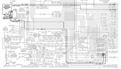
I think my headlamp door motor has a short somewhere and I can't find it... I've read the wiring diagram but now I know less then before...

I already separated the wires of interest.
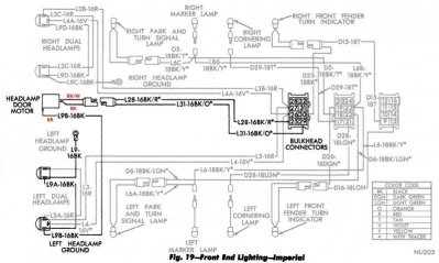
wd01.jpgwd02.jpg

What I know is, that the brown cable is my ground. The other two cables are going throught the bulkhead into the Hidden headlamp relay. And there, I'm out...

Is the relay directly operated by the headlamp switch in the dashboard to switch current from one cable to the other (BK/W - BK)? If so, there should be no connection between these two cables at any time, right?

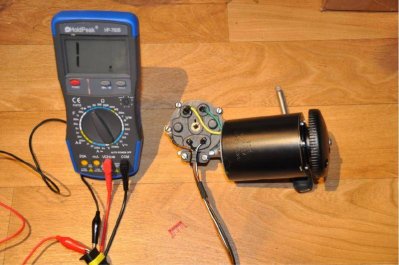
I have a good connection from Black to Brown until I turn the motor all to the left until the switch in the motor cover opens up.
Black+brown01.jpgBlack+brown02.jpg

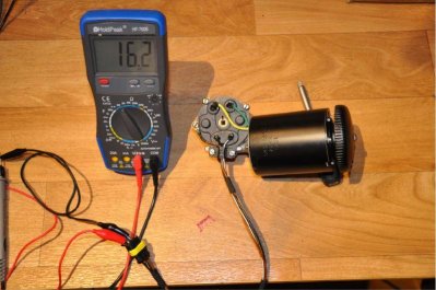
I also have a good connection from Black/White to Brown until I turn the motor all to the left until the switch in the motor cover opens up.
Black-white+brown01.jpgBlack-white+brown02.jpg

BUT I also have a connection with more ohms from Black/White to Black on the travelway beneath the two cover contacts. All the way to the left and right is obviously no connection because the shut off switches are open there.
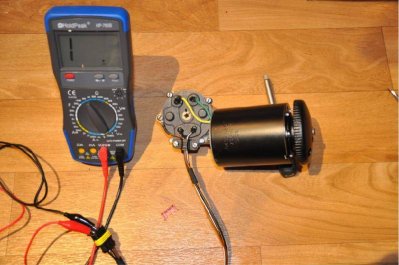
Black-white+black01.jpgBlack-white+black02.jpgBlack-white+black03.jpg

I hope my "descripion" is not too confusing... :O and someone can tell me where my problem is and how to solve it, or even how to measure correctly and what the numbers are meaning.

As I said, I'm a total noob to all the electric stuff but willing to learn in!


p.s. Next to the multimeter, I also bought a power supply to test all the stuff. But my guess, after I saw it in person, is that the 3A it's delivering are way to weak to start this big ol' motors... Is that right or not? How much ampere does such a motor need to start?
a (1).jpg

wd02.jpg


wd01.jpg


Black+brown01.jpg


Black+brown02.jpg


Black-white+brown01.jpg


Black-white+brown02.jpg


Black-white+black01.jpg


Black-white+black02.jpg


Black-white+black03.jpg


a (1).jpg
 
Would be much easier, indeed. But point one is, I saw a lot of refurbished motors and I'm not happy with wat I saw unless I'm not willing to pay $400+. The other thing is I have a lot of parts I have to repair. To buy them all new would be too expensive in my eyes. But the most important reason is, I have a lot of fun in doing what I'm doing ;)
 
"But the most important reason is, I have a lot of fun in doing what I'm doing ;)"
As we say in America..
F*****g A-right!!
 
I don't think your 3 amp power supply has got enough *** to drive the motor.

A battery charger is a decent alternative.
 
I will try the battery charger, good idea! Thanks. But I have to find the gremlin first to not kill the motor or the fuse in the charger! Any ideas and/or explanation on how the motor is working?
 
Testing continuity like you are doing might not tell you what you want to know. I'd have to really know how it all works and not be quite as tired as I am now to figure it out, but you may be showing continuity because of position of the commutator. Either way, I think a test by applying power will tell you much more... like if it works or not.

Was it working before you pulled it off the car?

I would first consult the FSM because I seem to remember there is a setup procedure about what position the motor is in before powering it up.

To prevent letting the smoke out when bench testing it, put a 10 amp fuse inline with your power wires.
 
I was under the impression that if the motor is operated without being hooked up to the headlight doors, and the dash switch, that you can strip the gears out, and/or burn out the motor. I think I remember reading somewhere, some time, that the motor needs the stops and resistance the other parts lend to the system to operate properly?

So until you have double checked procedures in the FSM, or perhaps someone who knows for sure will chime in, I would not try and power the motor into operation.
 
I read in the FSM I have on disk here, (not looking at it right now though) that you should not run the motor without it being connected up in the car with the doors. If you do it over rotates and bends the spring loaded plates that are used to cut off the motor and they are hardened material, meaning if you try to bend them back into position they can snap. I went through this in a 1970 Sport Fury headlight setup that uses the same motor. Check the FSM, I will look mine up and see if I can upload a picture of the section for you.
 
I was under the impression that if the motor is operated without being hooked up to the headlight doors, and the dash switch, that you can strip the gears out, and/or burn out the motor. I think I remember reading somewhere, some time, that the motor needs the stops and resistance the other parts lend to the system to operate properly?

So until you have double checked procedures in the FSM, or perhaps someone who knows for sure will chime in, I would not try and power the motor into operation.

That rang a bell and I looked in my FSM for my 70 and it does specifically say it will damage the motor to bench test or test it without being hooked to the doors.
 
Vodka, I just spent the last, nearly, 2 hours reading your thread... WOW. This is a big thread for a big car.

Anyway. VERY impressive work. you re getting this yacht set straight.
 
Testing continuity like you are doing might not tell you what you want to know. I'd have to really know how it all works and not be quite as tired as I am now to figure it out, but you may be showing continuity because of position of the commutator. Either way, I think a test by applying power will tell you much more... like if it works or not.

Was it working before you pulled it off the car?

I would first consult the FSM because I seem to remember there is a setup procedure about what position the motor is in before powering it up.

To prevent letting the smoke out when bench testing it, put a 10 amp fuse inline with your power wires.

I unfortunately don't know much about electrics. I only got a short indroduction from a friend. I first tested it with the current flow tester function (the peep thing) to check if I have a connection and then with the Ohm meter to check how good the connection is. Not right?

Because of a bad battery and a lot of redent damage on the wiring harness, I couldn't check anything in the car. But with all the rust on the inside of the motor, it was probably better anyway ;)


I read in the FSM I have on disk here, (not looking at it right now though) that you should not run the motor without it being connected up in the car with the doors. If you do it over rotates and bends the spring loaded plates that are used to cut off the motor and they are hardened material, meaning if you try to bend them back into position they can snap. I went through this in a 1970 Sport Fury headlight setup that uses the same motor. Check the FSM, I will look mine up and see if I can upload a picture of the section for you.

I have the digital FSM from the CD as well. Just took a copy of the PDF onto my PC. Much easier!

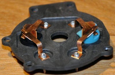
The contacts are not spring steel but they are bent down onto the black and blue rotating mechanisms in the cover to a very specific preasure. I spent over an hour to bent all four contacts to the very specific preasure they need to work. To loose and rotating plastic is wobbling around and the gear is just puching them sideways, to tight and the are spilling off of the plastic. Both ways, they are not opening up.

Headlamps - Motor - 103.jpg


I was under the impression that if the motor is operated without being hooked up to the headlight doors, and the dash switch, that you can strip the gears out, and/or burn out the motor. I think I remember reading somewhere, some time, that the motor needs the stops and resistance the other parts lend to the system to operate properly?

So until you have double checked procedures in the FSM, or perhaps someone who knows for sure will chime in, I would not try and power the motor into operation.

That rang a bell and I looked in my FSM for my 70 and it does specifically say it will damage the motor to bench test or test it without being hooked to the doors.

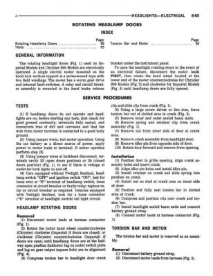
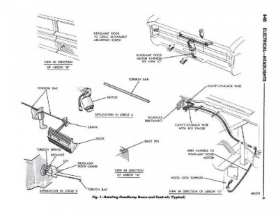
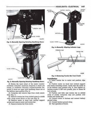
Here is the chapter about the hideaway headlamps (only 3 pages) but I can't find a part about not bench testing it. But I trust you on that, I definitely will NOT junk my motor..!
a.jpgb.jpgc.jpg

The halfway open position you and the FSM are talking about was already marken in my previous post in the messering photos with black and red lines. Not good visible tho... Here is a close up of the marks.
DSC_0002.jpg

a.jpg


b.jpg


c.jpg


DSC_0002.jpg


Headlamps - Motor - 103.jpg
 
Back
Top