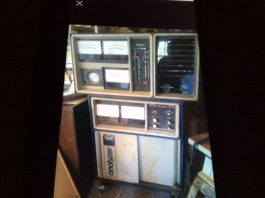
New project: Allen Engine analyzers, restoration?

I received my service manual for my 16-000, so I decided to tear down my 15-000 exhaust gas analyzer. I couldn’t stand not knowing what all was in there. :realcrazy:
Actually it doesn’t loo that complicated. Although I have no Idea how the nuclear reactor tubes with the glass ends and the mirrors work yet.
It consists of the exhaust sniffer inlet running through an air pump through a filter, T’s off with one end going to a diafram sensor (Or it could be a pressure regulator that controls the air pump). The other T outlet goes into a cooler or condenser of sorts and flows through the nuclear reactor ( glass tubes with mirrors) and then flows out of the machine. It is quite interesting, but not sure how every thing works yet. Will take apart, blast the cabinet and do some body work while I am trying figure it all out.

BA39CE76-64A2-438D-8348-E0AF870C5F1B.jpeg
9D874A37-2A21-49A0-B88E-590EC1160C18.jpeg
image.jpg

image.jpg
 
I am learning the correct terminology. They are not nuclear reactors, but a sample and reference chamber. The reference chamber is filled with nitrogen which infrared does not pick up so it is optically clear whereas the exhaust gasses in the sample chamber CO and HC can be seen by infrared. There are two mirrors a collimating mirror and a focusing mirror to reflect the parallel radiant infrared energy to a focal point onto the detector assembly. A chopper disk opens and closes the beam at a certain frequency creating a sine wave and converting to voltage to move the gauges. Easy Peasy.....
I don’t understand all the science, but have a better understanding. Hopefully enough to troubleshoot. First mission is to clean everything up.
Anyway a rough diagram.
View attachment 381536
Good description!
I worked on a device called a flame photometer, that used photodetectors, optical filters and burning known diluted ratios of blood, urine and other liquids to measure the concentration of potassium, sodium and lithium. I also took 1.5 years of physics in college (1 semester of optics) as well as worked on infrared and optical trackers in weapons systems. What you stated makes sense to me. Good luck on learning more and getting the equipment up and running!
 
Did some more disassembly, the air pump was stuck. Decided to tear it apart. Air diaphragm is pretty stiff and has years of exhaust deposits. I am thinking that since it is a simple diaphragm pump I should be able to find parts.
62996026-3F1A-48AB-9C0C-215D8D709F4F.jpeg
4E2AF15A-A195-4F7B-AE64-F353E1856F57.jpeg
98710679-0359-45C9-8BF8-5A8EA486CC4E.jpeg
 
I cannot bring the Vacuum pump back to life. The diaphragm is pushed out from the pump sitting in the upward stroke for many years. Since it is extended on one side it jams the motor on the upward stroke. I searched the model and could not find a kit. The manufacturer says parts for this model no longer exist. He did recommend a replacement pump. Original was a Thomas 106ca14/644TFE, Closest replacement was a 107CAB14TEFL. These are Teflon coated to keep them from carboning up. Frame size is the same. Initially I was thinking I might be able to use a diaphragm kit from the newer model, but I found a used pump shipped on E bay for $75. The kits I found were $70-$90.
I am going to make this work yet.
$95 plus gas into these so far. @Polara_500 is winning with the $20 in his pocket from these machines, but maybe I am winning too as I am learning a lot about diagnostics and tuneups by rebuilding these.
Next step is some body work, blasting and re painting. I will need to mask off the decals. I really doubt I will find replacements in my lifetime.
I like your ‘can do’ attitude!
 
I cannot bring the Vacuum pump back to life. The diaphragm is pushed out from the pump sitting in the upward stroke for many years. Since it is extended on one side it jams the motor on the upward stroke. I searched the model and could not find a kit. The manufacturer says parts for this model no longer exist. He did recommend a replacement pump. Original was a Thomas 106ca14/644TFE, Closest replacement was a 107CAB14TEFL. These are Teflon coated to keep them from carboning up. Frame size is the same. Initially I was thinking I might be able to use a diaphragm kit from the newer model, but I found a used pump shipped on E bay for $75. The kits I found were $70-$90.
I am going to make this work yet.
$95 plus gas into these so far. @Polara_500 is winning with the $20 in his pocket from these machines, but maybe I am winning too as I am learning a lot about diagnostics and tuneups by rebuilding these.
Next step is some body work, blasting and re painting. I will need to mask off the decals. I really doubt I will find replacements in my lifetime.
One of my few wins when it comes to automotive shtuff....... :drama:
 
I received my new used vacuum pump today. It seems to work fine and pulls the vacuum gauge down to around 18”.
The only issue is that it was listed as a Teflon coated (Tfel after the model number) but it is not. From what understand the Teflon prevents corrosion in the pump. I could send it back, but probably out $25 of shipping plus what cost to send back. For as much as I will run this it is probably ok. After running a test I will have to learn to let the pump run for a while on fresh air to clear it out.
0E3E0895-C047-416E-80F6-57B0B96CDBFA.jpeg
 
If the wind would ever stop blowing I will set up my sand blaster and clean up the cabinets. I will have to do a good job masking the decals so I don’t ruin them. The paint match may be difficult. It is almost a blue white or gray white color. I am thinking of trying a couple of grey coats and a lighter white coat to see if it gives me the right tone.
 
Decided to strip the paint using citrus remover.
It did really well on some parts but so so on others. I will sand the rest of the outside, but probably blast the inside.

I was able to use a heat gun to remove and salvage the decals. I need to figure out an adhesive to put them back on. For now they are stuck on some plexiglass.

C4506BB5-DDCD-4F3C-8E4A-B90A3D6715A3.jpeg
D963B60B-902F-49DD-9AB3-0DDF6D215A05.jpeg
0EB1A450-9519-4A56-8DF1-BAF447581EC7.jpeg
A8B94640-C0A4-40FF-9515-AF19C7A52683.jpeg
5DB532D7-04C4-412B-B0DE-37D563E87E7C.jpeg
92AA0034-309A-4CF4-A5F3-553205ADBBA4.jpeg
D109953E-B8BB-43EB-9E9C-CE9F9FF6EAD5.jpeg
 
I picked up a couple of Allen engine analyzers from @Polara_500. They were taking up space in his garage and I thought I needed a new project. I am not sure yet who the winner is. :rolleyes:
They are now taking up space in my garage. My desire is to clean them up / restore and get them working. I don’t know much about engine analyzers so I guess it is time to learn.
Models 15-110 and 16-130.
The 15000 has an exhaust sniffer
We believe they are early ‘70s. I did find a pdf version of the operating instructions and a training course on E-bay. It would be nice to find a service manual.
If anyone has more knowledge about these units I would be interested to hear it.
I plan to do some research before I tear into them too far.
They Don’t have the bright colors of the Sun analyzers, but I am going for function over form for now.

View attachment 314493 View attachment 314494 View attachment 314495 View attachment 314496 View attachment 314497
 
Looking for any info regarding your Allen engine analyzer.I just acquired this unit and would really appreciated any literature on operating procedures and also any pdf version of operating and instruction & training coarse.2D4A31C4-B7A1-461D-BFD1-0E0CD56AC07E.jpeg
 
Let me do some searching. There was a guy from Finlayson MN on E-bay that has CD's with many of the training manuals and operating manuals for some of the Allen analyzers.
You can find Sun manuals all over. The Allen one's are real difficult to find support.

Do you happen to know where one can find a spare gauge indicator? I spiked one of my gauges incorrectly testing it and it shattered the pointer.
 
Prices have gone up, but it looks like he has more manuals. It seems he packages a lot of items on the CD's beyond just the manuals. It looks like he has the gas analyzer one now.
This was the only source I have found.

allen test products bar 74,80 2 gas analyzer 23,000 service manual pdf book | eBay
I got my Allen engine analyzer up and running. I found a Burnt fuse and 3 broken wires . I’ve tried to install all the the hoses for the gas tester. If you have a photo of all the hoses hooked up could you send me a photo showing me the gas flow thru the system. Thank you
 
I got my Allen engine analyzer up and running. I found a Burnt fuse and 3 broken wires . I’ve tried to install all the the hoses for the gas tester. If you have a photo of all the hoses hooked up could you send me a photo showing me the gas flow thru the system. Thank you

I may have some pictures before I unhooked them all. It is in pieces right now. I will look through my picture files.
I still haven’t been able to get my gauges (voltage, amps…..)to respond on the upper part. Oscillation scope works well though.

Hopefully we get a garage sale over next weekend so I get one of my work spaces (third stall) back.
 
Here is what I found for mine. Top inlet is to hook up Co2? For calibration. Middle is for the hose that goes into the exhaust. I don’t recall what the bottom one is. I think it may be outlet for the analyzed gas or condensation drain.
I do also have pictures of the internal routing, but will take some puzzling over the pictures an manual to remember.
768AAE08-E49A-473C-97AB-E91631DEFD84.jpeg
F42D035B-4BE7-4191-97F0-807929C5F0F9.jpeg
83496F5B-7673-4FF2-BB42-9E353CB7A412.jpeg
 
I may have some pictures before I unhooked them all. It is in pieces right now. I will look through my picture files.
I still haven’t been able to get my gauges (voltage, amps…..)to respond on the upper part. Oscillation scope works well though.

Hopefully we get a garage sale over next weekend so I get one of my work spaces (third stall) back.
Here are a few photos of my Allen analyzer
I received my service manual for my 16-000, so I decided to tear down my 15-000 exhaust gas analyzer. I couldn’t stand not knowing what all was in there. :realcrazy:
Actually it doesn’t loo that complicated. Although I have no Idea how the nuclear reactor tubes with the glass ends and the mirrors work yet.
It consists of the exhaust sniffer inlet running through an air pump through a filter, T’s off with one end going to a diafram sensor (Or it could be a pressure regulator that controls the air pump). The other T outlet goes into a cooler or condenser of sorts and flows through the nuclear reactor ( glass tubes with mirrors) and then flows out of the machine. It is quite interesting, but not sure how every thing works yet. Will take apart, blast the cabinet and do some body work while I am trying figure it all out.

View attachment 381355 View attachment 381356 View attachment 381357
View attachment 381365
2CC14CCA-E555-497B-99D3-3D7B5E0348F1.jpeg295D8670-FCA8-4B2F-913A-9B71A690EF21.jpeg2CC14CCA-E555-497B-99D3-3D7B5E0348F1.jpeg
50E16D5D-E64E-4ECD-BD56-94D2FD82308C.jpeg
2CC14CCA-E555-497B-99D3-3D7B5E0348F1.jpeg
18ADC53B-1C05-4DCA-BE30-C12BB2B4BB62.jpeg


48D96344-1C83-414C-9860-3BD20DD0B28D.jpeg


5CAE4760-41EA-4510-9D64-E9B5DDF18645.jpeg


84442E9C-C022-4A0B-9A66-2998E0CB86BD.jpeg


88D69967-4669-444A-A954-2E6667FD07F6.jpeg


67C448B9-F6C1-4143-B475-46F903187294.jpeg


97546479-484B-4A02-B7B7-FF1DD5FDB2C6.jpeg
 
Back
Top